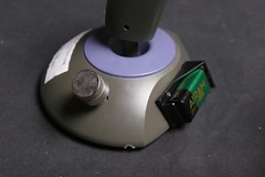
Noistick- create a noise making device from a joystick with autofire

This is experimental electronics project to turn your old joysticks into nice sound devices with no external sound source needed.
What you need to build this project:
1.Potentiometer (commonly pc or mac) joystick with autofire circuit. (C64, Atari and some other old joystics are different and there are no potentiometers inside them.)
Here in Finland these you can find these very cheap from fleamarkets. You recognice them from smooth and quite long movements of the stick and of course a switch that says autofire or turbofire.
The autofire circuit will act as oscillator and joysticks horizontal and vertical movement will be wired to control it.
2. soldering iron and a screw driver
3. some wire (or use the wire from joystick)
4. 9v battery and battery clip or a battery holder for 2-4 AA batteries
You might have problems fitting these inside the joystick. Make an external battery compartment.
5. some capacitors, resistors and diodes (recycled components from old broken electronic devices will do fine)
6. amplifier.
Small active computer speakers are probably the cheapest test amps you can find.
7. wires with alligatorclips (very useful when doing experiments)
8. output jack.
Open your joystick to see what is inside.
1. transistor based (No example here, but read through this article and start experimenting with these too. )
2. 555 based
3. cmos based
In this project we use 555 or cmos based circuit because they use only few components (In most cases 1 ic, 1 capacitor an 1 resistor) and are easy to do. When adding new components to circuit try different values with alligatorclips.
555 timer
step1. power it up
To power this circuit battery + needs to be connected to pin 8 and ground (-) to pin 1 . In some cases the connections for + and ground are marked on the pcb. If not you can easily follow the copper traces under the board. At this point use alligatorclips to power your circuit.
step2. how to hear if it works
When the circuit is powered correctly you can probe the circuit with alligator clips connected to input of your test amplifier. Pin 3 is output in the 555 circuit, just follow the copper traces on the pcb. You should be able to find ticking or motor running type sound. The oscillator is running quite slow because of the original timing network (resistors and capacitor).
diagram1. 555 oscillator inside the joystick
step3. make it adjustable
To make the sound adjustable remove resistor R1 and replace it with either x or y potentiometer inside the joystick (or both in series to get wider range). You can also change the capacitor to change the scale of the oscillator (larger values to get lower and smaller values to higher frequencies. Experiment different values)
After the resistor is removed solder two wires to the points where resistor was connected. Then solder other ends to one of the two potentiometers. One wire to middle pin and one to side pin. You might want to solder a resistor in series with the potentiometer so that the oscillators scale stays in audible frequency (try different values to find which value you need). Now moving joystick will change the frequency of the sound.
diagram 2. x potentiometer wired to make the oscillators frequency adjustable
step4. output
Solder a capacitor between the output wire from circuit and output jack. The signal is quite strong so you might want to add volume control -> a resistor, trimmer or potentiometer to output line.
WARNING.I do not recommend that you to plug this or any other experimental sound devices to your most expensive hi-fi audio equipment. You might end up having broken expensive hi-fi audio equipment.
step5. modulation input
You can feed external modulation signal to the 555 ic. Simply solder a wire between a input jack and pin 5 on the ic. Modulation signal needs to be quite strong. If you build two noisticks you can use one to modulate the other. As always-> experiment to get the best results.
step6. buttons
There are many possibilities to use the buttons. You should think what functions you need. Here is an example: Run the + wire through a button to the pcb. The circuit will be powered only when the button is pushed. Then add a electrolytic capacitor between the button connections (caps + connection to battery side). Now when the button released sound keeps on going for awhile (big capacitor values produce longer sound )
step7. Make some noise
After all wires, components etc. are soldered properly and everything seems to be working. Close the screws and your noistick is ready to annoy people around you with its horrible sounds.
cmos hex inverter
This type is the most fun because you can easily build more than one oscillator around the chip. So you can have an individual oscillator for x and y movements of the joystick with adding just few components. Only two different circuitry is presented here. You may (and probably will) find various others. Same principles can be used to many other joysticks with hex inverter based circuitry.
Both two joysticks use cmos hex inverter. First circuit uses 4069 second uses 74hc04 and the following instructions apply to these particular joysticks (the ic:s have same pinouts). If your joystick uses different ic than 4069 or 74hc04 you should check the pin connections and other information from datasheets (you can find them on the web)
step1. power it up
To power this circuit battery + needs to be connected to pin 14 and ground (-) to pin 7. Sometimes the connections for + and ground are marked on the pcb. ATTENTION! Some joysticks use 74hc…
marked chip (like the second example: 74hc04 hex inverter) It will fry if powered with 9v! With these use two to four AA batteries instead. Follow the copper traces on pcb to see witch wires go to these pins or solder new wires for battery. Make sure you connect the power correctly because wrog polarity can kill the cmos ic.
step2. how to hear if it works
When the power is connected correctly you can probe the circuit with alligator clips connected to input of your test amplifier. You should be able to find ticking type slow squarewave sound.
diagram 1. 74hc04 oscillator inside joystick 2. c1 and r1 create the timing network. pin 7 is connected to ground. pin 14 to battery +
diagram 2. 4069 oscillator inside joystick 1. c1 and r1 create the timing network. pins 1, 3, and 7 are connected to ground. pin 14 to battery +
step3. make it adjustable
To make this sound adjustable just remove the timing resistor (R1) and replace it with either x or y potentiometer inside the joystick. You can also change the capacitor (C1) to change the scale of the oscillator (larger values to get lower and smaller values to higher frequencies).
After the resistor is removed solder two wires to the points where resistor was connected. Then solder other ends to one of the two potentiometers. One wire to middle pin and one to side pin. You might want to solder a resistor in series with the potentiometer so that the oscillators scale stays in audible frequency (try different values). Now moving joystick sideways or up and down will change the frequency of the sound, depending on witch potentiometer is wired .
step4. second oscillator
4069 circuit
Cut the traces from inverter to ground from pin 1 and pin 3. Also cut the trace between pins 8 and 5. Now the output of your first oscillator will be from pin 8 and you have ½ of the chip free. Now solder a capacitor between pins 1 and 4, connect pins 2 and 3 with a drop of solder, connect pins 4 and 5 with a drop of solder, wires from the unused potentiometer are connected to pins 1 and 6
74hc04 circuit
The original circuit uses ½ of the chip to create the oscillator. The three remaining inverters will be used to create the other. You can copy the first oscillators circuit: a capacitor between pin 13 and 10, connect pins 12 and 11 with a drop of solder, connect pins 10 and 9 with a drop of solder and the remaining potentiometer between pins 13 and 8. When completed the circuit is the same as on the 4069 joystick. And here is the diagram.
diagram 3. two oscillators wired to joysticks x and y potentiometers
step5. output and mixing
diagram 4. The mixing network either with resistors (left) or with diodes (right)
You can mix the signals to a single output from the two oscillators with resistors or diodes. Try both and choose the mixing network you like. Or you can use stereo output connecting one oscillator to right channel and one to the left channel. Solder a capacitor between the output wire from mixing network and output jack. The signal is quite strong so you might want to add volume control -> a resistor, trimmer or potentiometer to output line.
step6. buttons.
In most joystick there are two buttons. You can run the output from each oscillator before the mixing network through individual button. Now by pushing one button you can hear one osc and pushing both buttons you can hear them both. (See also 555 timer joystick step6. buttons)
step7. make some noise.
After all wires, components etc. are soldered properly and everything seems to be working. Close the screws and your noistick project is completed.


.jpg)


