you may have heard about: Wave Vessel, Wobblevision, Analog Visualization Unit, AVU, Psychoscope, o-scope, b&w tv into a large screen oscilloscope kits...etc...
This is it all in one.
Before we begin, I have to give everyone a warning.
DO NOT ATTEMPT THIS PROJECT!
MODIFYING TV IS A DANGEROUS PROCESS.
DO NOT ATTEMPT THIS UNLESS YOU KNOW THE DANGERS OF CAPACITORS AND
OTHER ELECTRONIC COMPONENTS. THERE IS A GREAT RISK OF POTENTIALLY
DEADLY ELECTRIC SHOCK, AND THERE IS THE POSSIBILITY OF FIRE OR EXPLOSION.
IF YOU TRY TO FOLLOW THESE INSTRUCTIONS, NO-ONE CANNOT BE HELD LIABLE
FOR ANY DAMAGE OR DEATH CAUSED WHILE BUILDING OR USING THE DEVICE
Before you begin read these safety instructions:
Safe Discharging of Capacitors in TVs and Video Monitors
Cathode-ray tube Safety Issues
Deflection System Safety
 There are two areas which have particularly nasty electrical dangers:
the non-isolated line power supply and the CRT high voltage.
Stay away from the red cable with the suction cup end.
After you have opened the TV unit wear rubber gloves!
(longer sleeves better)

The principal of this audio signal displaying is that when TV is normally operated the Deflection Yoke generates a magnetic field and use it to direct the electron beam in the cathode-ray tube.
Deflection Yoke gets signals from deflection circuit. Two of the wires control the horizontal motion, and the other two
control the vertical motion. You just replace the Deflection Circuit
signals whit amplified audio signals and then controll the beam by the audio signal.
I have made some schematics to clear how to route audio signals to
Deflection Yoke- these
schematics are based on information from censtron.com Wave Vessel page and my own experiments.
first you need to find out the two horizontal and two vertical wires.
these instructions on Censtron page will help you
 "The diagram above shows all six possible wire combinations. The diagram is drawn from the angle of looking directly at the back of the tube. The colors I used are just for reference,and may be different depending on the model of the television."

"First clip and strip all four of the wires going to the tube, then connect them all back up using alligator clips.
Then, remove one of the clips, and turn the television on. If you get a vertical line, then the disconnected wire is one of the horizontal drive wires, if you get a horizontal line, then you disconnected a vertical wire. Turn the television back off, then follow the same process for the other
three wires to determine which direction each controls."

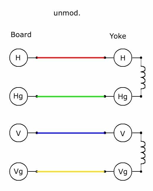
Here you see the wires going to yoke ->
H=horizontal
Hg =horizontal ground
V=vertical
Vg=vertical ground
Here is the unmoded version:
Whit this you can see normal TV programs.
Here is the Censtron version (a
Whit this setup you get a bar that differens in length
a bit like panel of KITT [the car from Knight Rider]

Here is the Censtron version (b
Whit this setup you get vertical line that vibrates.


Here is the stereo version.
Whit this setup you get pulsing circles

After reading this post on audiokarma.org
i decided to ad second yoke...
quote: DBerning on audiokarma.org
"Magnetic deflection TVs of this era needed the deflection yoke for energy storage for the flyback pulse
that was used to provide high voltage for the CRT. Because I was using the yoke for audio
deflection, I mounted a second deflection yoke somewhere in the TV cabinet so that the inductance
from the winding could be used in the flyback-based high-voltage circuit."
Here is my Philips TX:

One month later:
Okay i did find the extra yoke but, it was not the right type.
This is what happened:
The picture was extremely bright! i mean really really bright.
I was very happy for a while, it looked so cool. After some 15 -30mins both of the TV sets
fuses were burn and the unit was extremely warm. Then i noticed there was a X-ray warning on the tube :" do not drive the CRT whit too much current/voltage or it will start produce X-rays.
So what i assume happened is that i drived the CRT whit too much voltage/current and it started to produce X-rays!
What did we learn?
If you want to ad the extra yoke to extra brightness you need to
measure the yokes inductance first and then find another yoke that has
the same properties.
(or if you want a cheapo X-ray machine just replace the fuses whit thick wire);)
Day later:
I'm feeling lot better now
i called to The Radiation and Nuclear Safety Authority of Finland and asked
if i have been exposed to any radiation danger by moding my TV. They said that there is very
small possibility to get enough radiation from CRTs - in their test
the maximum X-ray radiation from television has been 100mGy/h (hundred milliGrays per hour)
and after that the tube has collapsed.
To get symptoms from X-rays you need to get at least 100Gy.
The symptoms are then the same type of skin burns you get from sun.
The X-ray radiation on tv-set is stronger in the back of the tube than
in the front. The X-ray born's when electrode hits the phosphor wall.
X-ray bounces back to the inner walls of tube. it keeps bouncing and gets weaker and dies.
The glass is thicker in the back so some x-rays get through but we are talking of
really small amounts of radiation.
After replacing the fuses i tryed it again, so i connected the coil
to the points of horizontal and horizontal ground of the Deflection
Circuit(Board) - and wow it was cosmic again. - the beam was so bright - it was just like looking to sun.
well i realized that the unit heated a lot - so i attached two ventilators . . . and i took it to "koneisto" (
The Festival For Electronic Music in Helsinki) it was on stage whit Aavikko. It lasted one hour,
almost the whole gig and died of over heating. I have to say that no TV has ever be so bright!
all the time it looked that it will explode any minute :)
this is the setup what i did
so i have been looking for the next TV (victim) to my experiments. I got now a correct size coil from the broken Philips TX.
Meanwhile Censtron has made their first color vessel:
"We just finished making the first Color Wave Vessel, with it you can now make the visualizations any color from invisible to white."
Two months later:
My Friend gave me a old soviet travel-TV that was not working but, it could display the usual noise.
I did the things described in this article (whitout the extra coil)- whit a 2mm pinjack -patch panel and speakon connector - so i can connect straight to my amp.
here are some pictures:

not much space inside so i removed the speaker
The patch panel made of perspex:
the whole unit:


This video shows the beauty of electron beam bouncing whit music
UPDATE:
I tryed whit a color unit and gues what, it's really easy, the scope mod its the same as whit B/W tv's and the color adjuts mod is done by soldering of three potentiometers from the back of the PCB that's in the back of the CRT. and mounting new potentiometers to the case. here is a pic of the pots that needs to be taken of and replaced by a same value.

here is the color unit in action, Photo by Tomi F

Some links to DIY Oscilloscope's
http://www.intio.or.jp/jf10zl/tvosc.htm
instructions to make GBDSO (GameBoy Digital Sampling Oscilloscope)
http://www.reinerziegler.de/gbdso_uk.pdf
LED-matrix oscilloscope
http://www.geocities.com/SiliconValley/Lakes/7156/articl3.htm
there is a neat how to on geek technique. org
how to make Mac se/30 audio visualizers
http://geektechnique.org/projectlab/707/how-to-make-mac-se30-audio-visualizers
Take care
Daniel
DO NOT ATTEMPT THIS PROJECT!
MODIFYING TV IS A DANGEROUS PROCESS.
DO NOT ATTEMPT THIS UNLESS YOU KNOW THE DANGERS OF CAPACITORS AND
OTHER ELECTRONIC COMPONENTS. THERE IS A GREAT RISK OF POTENTIALLY
DEADLY ELECTRIC SHOCK, AND THERE IS THE POSSIBILITY OF FIRE OR EXPLOSION.
IF YOU TRY TO FOLLOW THESE INSTRUCTIONS, NO-ONE CANNOT BE HELD LIABLE
FOR ANY DAMAGE OR DEATH CAUSED WHILE BUILDING OR USING THE DEVICE
Before you begin read these safety instructions:
Safe Discharging of Capacitors in TVs and Video Monitors
Cathode-ray tube Safety Issues
Deflection System Safety
 There are two areas which have particularly nasty electrical dangers:
the non-isolated line power supply and the CRT high voltage.
Stay away from the red cable with the suction cup end.
After you have opened the TV unit wear rubber gloves!
(longer sleeves better)

The principal of this audio signal displaying is that when TV is normally operated the Deflection Yoke
Deflection Yoke gets signals from deflection circuit.
control the vertical motion. You just replace the Deflection Circuit
signals whit amplified audio signals and then controll the beam by the audio signal.
I have made some schematics to clear how to route audio signals to
Deflection Yoke- these
schematics are based on information from censtron.com Wave Vessel page and my own experiments.
first you need to find out the two horizontal and two vertical wires.
these instructions on Censtron page will help you
 "The diagram above shows all six possible wire combinations. The diagram is drawn from the angle of looking directly at the back of the tube. The colors I used are just for reference,and may be different depending on the model of the television."
"First clip and strip all four of the wires going to the tube, then connect them all back up using alligator clips.
Then, remove one of the clips, and turn the television on. If you get a vertical line, then the disconnected wire is one of the horizontal drive wires, if you get a horizontal line, then you disconnected a vertical wire. Turn the television back off, then follow the same process for the other
three wires to determine which direction each controls."

Here you see the wires going to yoke ->
H=horizontal
Hg =horizontal ground
V=vertical
Vg=vertical ground
Here is the unmoded version:
Whit this you can see normal TV programs.
Here is the Censtron version (a

Whit this setup you get a bar that differens in length
a bit like panel of KITT [the car from Knight Rider]


Here is the Censtron version (b
Whit this setup you get vertical line that vibrates.


Here is the stereo version.
Whit this setup you get pulsing circles

After reading this post on audiokarma.org
i decided to ad second yoke...
quote: DBerning on audiokarma.org
"Magnetic deflection TVs of this era needed the deflection yoke for energy storage for the flyback pulse
that was used to provide high voltage for the CRT. Because I was using the yoke for audio
deflection, I mounted a second deflection yoke somewhere in the TV cabinet so that the inductance
from the winding could be used in the flyback-based high-voltage circuit."
Here is my Philips TX:

One month later:
Okay i did find the extra yoke but, it was not the right type.
This is what happened:
The picture was extremely bright! i mean really really bright.
I was very happy for a while, it looked so cool. After some 15 -30mins both of the TV sets
fuses were burn and the unit was extremely warm. Then i noticed there was a X-ray warning on the tube :" do not drive the CRT whit too much current/voltage or it will start produce X-rays.
So what i assume happened is that i drived the CRT whit too much voltage/current and it started to produce X-rays!
What did we learn?
If you want to ad the extra yoke to extra brightness you need to
measure the yokes inductance first and then find another yoke that has
the same properties.
(or if you want a cheapo X-ray machine just replace the fuses whit thick wire);)
Day later:
I'm feeling lot better now
i called to The Radiation and Nuclear Safety Authority of Finland and asked
if i have been exposed to any radiation danger by moding my TV. They said that there is very
small possibility to get enough radiation from CRTs - in their test
the maximum X-ray radiation from television has been 100mGy/h (hundred milliGrays per hour)
and after that the tube has collapsed.
To get symptoms from X-rays you need to get at least 100Gy.
The symptoms are then the same type of skin burns you get from sun.
The X-ray radiation on tv-set is stronger in the back of the tube than
in the front. The X-ray born's when electrode hits the phosphor wall.
X-ray bounces back to the inner walls of tube. it keeps bouncing and gets weaker and dies.
The glass is thicker in the back so some x-rays get through but we are talking of
really small amounts of radiation.
After replacing the fuses i tryed it again, so i connected the coil
to the points of horizontal and horizontal ground of the Deflection
Circuit(Board) - and wow it was cosmic again. - the beam was so bright - it was just like looking to sun.
well i realized that the unit heated a lot - so i attached two ventilators . . . and i took it to "koneisto" (
The Festival For Electronic Music in Helsinki) it was on stage whit Aavikko. It lasted one hour,
almost the whole gig and died of over heating. I have to say that no TV has ever be so bright!
all the time it looked that it will explode any minute :)
this is the setup what i did

so i have been looking for the next TV (victim) to my experiments. I got now a correct size coil from the broken Philips TX.
Meanwhile Censtron has made their first color vessel:

"We just finished making the first Color Wave Vessel, with it you can now make the visualizations any color from invisible to white."
Two months later:
My Friend gave me a old soviet travel-TV that was not working but, it could display the usual noise.
I did the things described in this article (whitout the extra coil)- whit a 2mm pinjack -patch panel and speakon connector - so i can connect straight to my amp.
here are some pictures:

not much space inside so i removed the speaker
The patch panel made of perspex:

the whole unit:


This video shows the beauty of electron beam bouncing whit music
UPDATE:
I tryed whit a color unit and gues what, it's really easy, the scope mod its the same as whit B/W tv's and the color adjuts mod is done by soldering of three potentiometers from the back of the PCB that's in the back of the CRT. and mounting new potentiometers to the case. here is a pic of the pots that needs to be taken of and replaced by a same value.
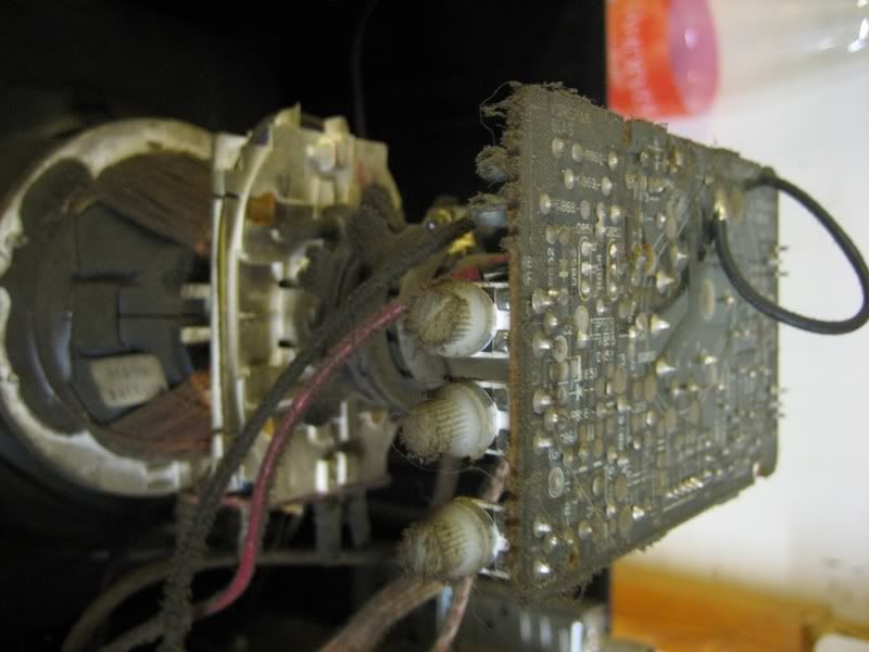
here is the color unit in action, Photo by Tomi F

Some links to DIY Oscilloscope's
http://www.intio.or.jp/jf10zl
instructions to make GBDSO (GameBoy Digital Sampling Oscilloscope)
http://www.reinerziegler.de
LED-matrix oscilloscope
http://www.geocities.com
there is a neat how to on geek technique. org
how to make Mac se/30 audio visualizers
http://geektechnique.org
Take care
Daniel


.jpg)


