Tuesday, October 16, 2007

WP-20 sound effects synthesizer


I have been building some noisemakers using cardboard as pcb. It´s a nice material for building electronic projects at home because: 1. everybody may not have the needed equipment to make "real" pcb:s 2. every one has a piece of cardboard laying around. 3. It is cheap and easy. This is my latest creation on cardboard pcb. It´s wp-20 sound effects synth. It was very nice to do on cardboard because there was enough spce between components in the original pcb design.

I did´t use the original noise source with 18v but i built a simple 9v noise generator. I left q1, r1, c3 unconnected to the board. here is the noise circuit.
output of the noise generator was connected to r3 through 50k resistor.

Testing wp-20 video:
link to music from outer space wp-20 page:


I made a sub oscillator for my wp-20. It is based on cd4040 ripple counter it uses the vco squarewave (before the 100k resistor marked R8 in the original wp20 schematics) as clock input and divides it. Six switches (from 1 octave down to 6 octave down) select the harmonics to vcf-vca. The circuit is quite simple the component values may be tweaked to get better performance. I used components that I happened to have so some different values might work better but these seem to work ok. (sub osc out is connected to ic 2b pin 6 through a 100k resistor like the vco) here is a picture of the circuit


Wednesday, June 6, 2007

Stereo tapedeck oscillator

This is a easy and quick way to make a feedback oscillator from old tapedeck. You just need to connect the rec input with output.

You can do it by soldering wires between the in and out lines (r in to r ou and l in to l out) Most homestereo tape players use rca connectors and you can use them as your outputs. You can also do this without soldering if you have proper wires to do the connections ( few rca wires and Y shaped rca adaptor for output from feedbackloop). Press rec/play to get it working. Frequency of the oscillator is adjusted by turning the tapedecks rec level knobs. The singnal is quite strong so I do not recommend you to plug this to your most expensive or fragile sound gear.

Wednesday, May 30, 2007

Mobile experimental electronics laboratorium

IMG_7023.JPG

This is a work in progress, we are just starting. For years we have been talking about a mobile experimental electronics platform, that we could drive anywhere. Now we have a solid base for that.

We were just given an electric car, Elcat. Our aim is to integrate mobile experimeltal electronics laboratory and facilities to play electronic sounds straight from the van. Idea is to integrate all essential features inside the van, so we just drive it anywhere we want to show our stuff.

IMG_7018.JPG

Project will propably advance quite slowly. The first obstacle on our way are the batteryes. The ones we have are in a pretty bad shape, and new set will cost us about 1000-4000 euros. Beside that we will have to pay quite a lot of money to get the car registered. Among other things we will have to pay DIESELL TAX for not using gas.

well project is advancing slowly, we should be getting the car toed to Vallila in couple of days, and after that we will start measuring, planning and of course we must start to gather money for this financially disasterous project.

Monday, March 5, 2007

Mc-7 progress

I´ve been working with my MC-7 for some time now and here is picture of it now

From left to right:

Pulse outputs module with led indicators: Four rhythm pulses (hi-hat, bassdm, snare, extra pulse : mirror to accomp Two from keypress : 1 note and second note: pulse depends on the chosen instrument. Second note output also follows accompaniment line when accompaniments are on.

Simple Low-pass Filter circuit (same as in music from outer space wsg)

36 point patch bay: made from amphenol connectors ( it is really easy to use with alligatorclips.)

Switch panel for cutting or connecting some original features: nice to redirect some signals in there.

Still plenty of work to be done. Next module will be some bending controls that are just too good to be left only for the patch bay. Also every time i open the keyboard and do some testing with the circuit board I end up soldering new wires to new points on the board... maybe i should add one 12 point amphenol to the patch bay.

Saturday, February 17, 2007

MC-7 keyboard


I found a nice keyboard from flea market yesterday. It was not in very good condition-> the drum section was completely silent. I opened it and found that some components were loose because of bad soldering work. After soldering these properly the drums started working.
The sounds of this keyboard are simple but very nice. All keyboard instruments are quite raw sounding squarewave. Drum sounds are short noise (hi-hat), smooth click (bass drum), and sharper click (snare).


Original features:
2 notes polyphony (monophonic if accompaniments are on)


Cotrol panel from left to right:


-power on/off switch
-accomp volume 4 way switch – this controls only volume of the drums not the accompaniment bass line
-master volume 4 way switch

Rhythm section:
-8 preset rhythms: disco, march, rock, waltz, pops, 16 beat, rhumba, bossanova
-accomp on/off button: the accompaniments are very simple and funny
-tempo buttons: slow and fast
-synchro button
-start button
-stop button

Orchestra section:
-8 preset instruments: clarinet, violin, oboe, piano, elec guitar, xylophone, harpsichord, mandolin
-sustain button
-vibrato button
-demo button

record section:
-record button: 28 notes
-play/stop button

Custom drummer section:
-3 drum pads: bass drum, snare, hi-hat
-program button: 16 steps
-play/space button

After some testing I found out that each of the three drum sounds are triggered from individual pins from the ic. There is also a fourth trigger pulse witch was unused in this model. I soldered wires from all 4 pins. Now I have 4 trigger output lines that follow the preset rhythms and three of them (bass drum, hi-hat and snare trigger signals) are programmable for 16 step sequences. These wires can be connected to various points on the pcb, when 1 or more of them are routed to the pins that read the buttons/keyboard you get many strange rhythmical bleeps and other crazy features like “bouncing” tempo and “random” notes and chords played.
I also found the output pins for keyboard sounds and the accompaniment sounds, these can be connected to various points on the pcb to change and modulate the sounds in many ways.Because the many possibilities of expanding the features of this keyboard I decided to build an extension case to fit the new controls, outputs, patch bay etc. So many ideas: adding a low pass filter circuit, new drum sound circuits to use with the trigger signals, joystick controller for some features, new buttons, switches and a patch bay…. a lot of decisions to make.

Well now I addad few wires (30 and counting) to different points on the pcb. All of these will be going to a patch bay so there is quite many possibilities to change the sounds and functions of the keyboard. Here is a picture.

The new wires from the pcb are soldered to a piece of stripboard so it will be easier to direct them to different controls and patch bay.


After some thinking and going through materials at our studio. I found the perfect extension case. It seems that I´m going for a modular design with this one. :)

Here is mc-7 posing with the extension case. I cut some new panels from red plastic. The alumnium panels were on the case.

Wednesday, February 14, 2007

Bending Yamaha PSR-6

I got my hand on Yamaha PSR-6 and of course I did bend it :)
here is the story, hope you can learn something.

after opening look for the big chips...


here are the two main chips the XE323B0 is CPU and YM2413 is the FM sound chip.
and the PCB side looks like this(note:image flipped around for better viewing):


there is nice information of YM2413
YM2413 FM Operator Type-LL (OPLL) Application Manual
and as far as i understand the CPU sends bits on eight data lines to FM chip and the sound's are made inside the FM chip...

after reading nice instructions on circuit-bent.net on bending PSS-270
I wanted to know more about the data flow between the CPU and FM chips. I installed LEDs that indicate if the pins are high of low, a kind of dataflow monitor.

some details:

wires attached to YM2413


wires coming out from little screw hole


transistor station


the leds and transistor station


And finally the schematic:

duplicate this 8 times.


here is a video of this thing running

next thing to do is the switches and the banana board.


here is my messy soldering but - everything is fine i checked whit multimeter - no short circuit's :)


and here is the 2mm mini-banana patch points (yellow -from CPU. green- to FM)


and here are switches for getting back to normal and for setting crazy settings


Quote, circuit-bent.net
"Each switch now controls the flow of data from the FM chip to the main chip. Turn the yamaha on and select a patch (let's pull up #89 "ghost"), I usually play some keys(don't know if you have to do this or not), then turn some switches off , now select a different patch, and turn the switches back on. Now try playing the new patch. If it went well some of the data from the all patch got held up, and then inserted into the new patch making a totally different sound. Sometimes leaving the connections off will change the sounds also. I've noticed them some of the bent up patches will only work when multiple keys are played. I've heard that this will effect the drums as well, but I haven't gotten it to do much with them as of yet"

after setting the bended tone - i messed around whit the banana patch -
it's sooo nice -
listen .mp3 sound samples

After making this I received some questions. Here are the questions and my answers:

Quote, mister.
"I have recently begun bending a Yamaha PSR-6. The only info I have found on bending for this model of keyboard was your's. I had a few questions if you don not mind. First I wanted to know how your particular approach came out (hoe pleased are you with the results). Second, I wanted some more info on your LED wiring. I have just begun learning more details on electronics and from what I saw on the forum I'm farely certain I know what you did, but more details would be nice. For example, what type of NPN did you use exactly? Also where the hell did you get those pin jacks? I have found some probes that look similar, but I don't know if there are any sockets for them. I have oredered RCA and will use those, but I like the pin jacks a lot and even if I don't use them on this project it would be cool for future work. Thank you for your time and much repect for your work from me. I hope you can afford the time to help me out. Any details you can give would kick ass."

Quote, sponge.
"hi there, i saw that you have successfully bend the yamaha psr-6. i picked one up the other day from a charity shop. im a little confused about what you were trying to do with it... sounded very cool though! would you be willing to tell me where the bends you found were, and what the LED / transistor circuits were for? i've found a couple of bends, but i've only bent one thing before, and that was a cheap effects pedal."


My answer:

Lets start whit the schematics and pics:

here are the main chips from the "solder side".
red dots are points D0 - D7 of the FM chip YM2413
and the blue dots are points D0 - D7 of the CPU chip XE323B0
yellow lines indicate where you need to cut the traces.

here is the YM2413 chip Pin Assignment:


here is the schematic:

you need to ad this circuit to all eight points (D0 to D0, D1 to D1 ...)

the transistors i used are C2389
- but you can use any general type NPN transistor. experiment whit the ones you have.


the bends i made are
1. 8 switches to control data flow
2. 8LEDs to monitor the data flow
3. data-patch bay to patch data

Haven't had much time to play whit my Yamaha but i must say that I'm pleased whit the results.

The method described in Kevin Rees site is good start.
here are some of my own that you can hear in the sample:
start whit sound 40, turn D0 off, change to sound 50 and turn the D0 on - start playing.
start whit sound 40, turn D7 off, change to sound 50 and turn the D7 on - start playing.
start whit sound 40, turn D0 off, change to sound 89 and turn the D0 on - start playing.

As you can now imagine there are MANY combinations .
after i have set a sound. i start patching - but that's not that easy - the monitor helps in this - but it crashes a lot - by trial and error you will learn :)

The D4 is used to trigger the sounds so if you have that turned off, nothing happens

The pin jacks i got from YEinternational but they only serve you in Finland, Russia and the Baltics. The pin jacks are made by Hirschmann. Maybe if you ask your local supplier if they have those 2mm pin jacks? they can arrange something.

About the LED data monitor.
Every time one of the points D0 -D7 goes high, LED D0-D7 goes on.
By looking the LED' s blink you can see the data flow and its easier to learn patching when you actually see whats going on in the inputs of the chip.

hope this helps

for more questions don't hesitate to post it here.

Daniel

Tuesday, February 13, 2007

Using TV to display audio signals.

you may have heard about: Wave Vessel, Wobblevision, Analog Visualization Unit, AVU, Psychoscope, o-scope, b&w tv into a large screen oscilloscope kits...etc...

This is it all in one.

Before we begin, I have to give everyone a warning.
DO NOT ATTEMPT THIS PROJECT!
MODIFYING TV IS A DANGEROUS PROCESS.
DO NOT ATTEMPT THIS UNLESS YOU KNOW THE DANGERS OF CAPACITORS AND
OTHER ELECTRONIC COMPONENTS. THERE IS A GREAT RISK OF POTENTIALLY
DEADLY ELECTRIC SHOCK, AND THERE IS THE POSSIBILITY OF FIRE OR EXPLOSION.
IF YOU TRY TO FOLLOW THESE INSTRUCTIONS, NO-ONE CANNOT BE HELD LIABLE
FOR ANY DAMAGE OR DEATH CAUSED WHILE BUILDING OR USING THE DEVICE

Before you begin read these safety instructions:
Safe Discharging of Capacitors in TVs and Video Monitors
Cathode-ray tube Safety Issues
Deflection System Safety

There are two areas which have particularly nasty electrical dangers:
the non-isolated line power supply and the CRT high voltage.
Stay away from the red cable with the suction cup end.
After you have opened the TV unit wear rubber gloves!
(longer sleeves better)


The principal of this audio signal displaying is that when TV is normally operated the Deflection Yoke
generates a magnetic field and use it to direct the electron beam in the cathode-ray tube.
Deflection Yoke gets signals from deflection circuit.
Two of the wires control the horizontal motion, and the other two
control the vertical motion. You just replace the Deflection Circuit
signals whit amplified audio signals and then controll the beam by the audio signal.

I have made some schematics to clear how to route audio signals to
Deflection Yoke- these
schematics are based on information from censtron.com Wave Vessel page and my own experiments.

first you need to find out the two horizontal and two vertical wires.
these instructions on Censtron page will help you
"The diagram above shows all six possible wire combinations. The diagram is drawn from the angle of looking directly at the back of the tube. The colors I used are just for reference,and may be different depending on the model of the television."


"First clip and strip all four of the wires going to the tube, then connect them all back up using alligator clips.
Then, remove one of the clips, and turn the television on. If you get a vertical line, then the disconnected wire is one of the horizontal drive wires, if you get a horizontal line, then you disconnected a vertical wire. Turn the television back off, then follow the same process for the other
three wires to determine which direction each controls."


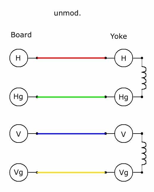
Here you see the wires going to yoke ->


H=horizontal
Hg =horizontal ground
V=vertical
Vg=vertical ground


Here is the unmoded version:
Whit this you can see normal TV programs.


Here is the Censtron version (a
Whit this setup you get a bar that differens in length
a bit like panel of KITT [the car from Knight Rider]


Here is the Censtron version (b
Whit this setup you get vertical line that vibrates.


Here is the stereo version.
Whit this setup you get pulsing circles


After reading this post on audiokarma.org
i decided to ad second yoke...

quote: DBerning on audiokarma.org
"Magnetic deflection TVs of this era needed the deflection yoke for energy storage for the flyback pulse
that was used to provide high voltage for the CRT. Because I was using the yoke for audio
deflection, I mounted a second deflection yoke somewhere in the TV cabinet so that the inductance
from the winding could be used in the flyback-based high-voltage circuit."


Here is my Philips TX:


One month later:

Okay i did find the extra yoke but, it was not the right type.
This is what happened:
The picture was extremely bright! i mean really really bright.
I was very happy for a while, it looked so cool. After some 15 -30mins both of the TV sets
fuses were burn and the unit was extremely warm. Then i noticed there was a X-ray warning on the tube :" do not drive the CRT whit too much current/voltage or it will start produce X-rays.
So what i assume happened is that i drived the CRT whit too much voltage/current and it started to produce X-rays!

What did we learn?
If you want to ad the extra yoke to extra brightness you need to
measure the yokes inductance first and then find another yoke that has
the same properties.
(or if you want a cheapo X-ray machine just replace the fuses whit thick wire);)

Day later:

I'm feeling lot better now

i called to The Radiation and Nuclear Safety Authority of Finland and asked
if i have been exposed to any radiation danger by moding my TV. They said that there is very
small possibility to get enough radiation from CRTs - in their test
the maximum X-ray radiation from television has been 100mGy/h (hundred milliGrays per hour)
and after that the tube has collapsed.

To get symptoms from X-rays you need to get at least 100Gy.
The symptoms are then the same type of skin burns you get from sun.

The X-ray radiation on tv-set is stronger in the back of the tube than
in the front. The X-ray born's when electrode hits the phosphor wall.
X-ray bounces back to the inner walls of tube. it keeps bouncing and gets weaker and dies.
The glass is thicker in the back so some x-rays get through but we are talking of
really small amounts of radiation.

After replacing the fuses i tryed it again, so i connected the coil
to the points of horizontal and horizontal ground of the Deflection
Circuit(Board) - and wow it was cosmic again. - the beam was so bright - it was just like looking to sun.
well i realized that the unit heated a lot - so i attached two ventilators . . . and i took it to "koneisto" (
The Festival For Electronic Music in Helsinki) it was on stage whit Aavikko. It lasted one hour,
almost the whole gig and died of over heating. I have to say that no TV has ever be so bright!
all the time it looked that it will explode any minute :)

this is the setup what i did


so i have been looking for the next TV (victim) to my experiments. I got now a correct size coil from the broken Philips TX.


Meanwhile Censtron has made their first color vessel:


"We just finished making the first Color Wave Vessel, with it you can now make the visualizations any color from invisible to white."


Two months later:

My Friend gave me a old soviet travel-TV that was not working but, it could display the usual noise.
I did the things described in this article (whitout the extra coil)- whit a 2mm pinjack -patch panel and speakon connector - so i can connect straight to my amp.
here are some pictures:


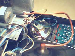
not much space inside so i removed the speaker


The patch panel made of perspex:


the whole unit:


This video shows the beauty of electron beam bouncing whit music


UPDATE:
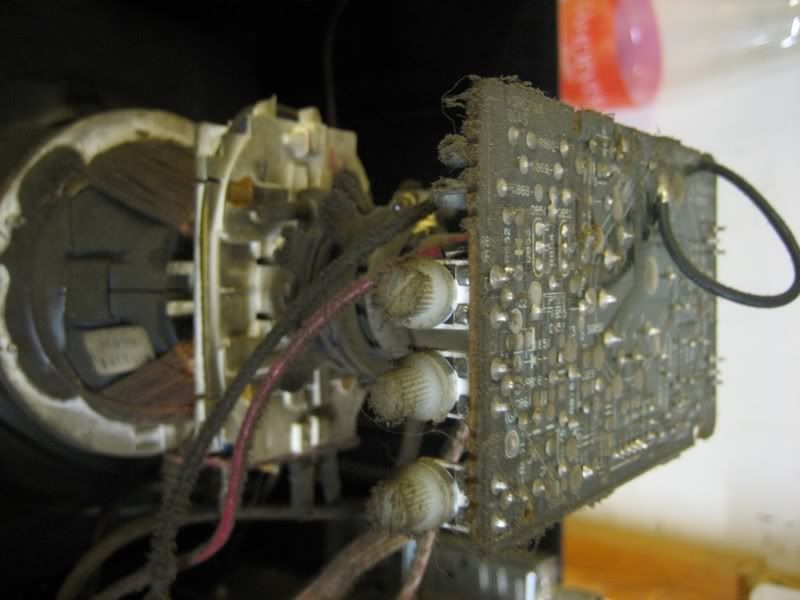
I tryed whit a color unit and gues what, it's really easy, the scope mod its the same as whit B/W tv's and the color adjuts mod is done by soldering of three potentiometers from the back of the PCB that's in the back of the CRT. and mounting new potentiometers to the case. here is a pic of the pots that needs to be taken of and replaced by a same value.


here is the color unit in action, Photo by Tomi F


Some links to DIY Oscilloscope's
http://www.intio.or.jp/jf10zl/tvosc.htm

instructions to make GBDSO (GameBoy Digital Sampling Oscilloscope)
http://www.reinerziegler.de/gbdso_uk.pdf

LED-matrix oscilloscope
http://www.geocities.com/SiliconValley/Lakes/7156/articl3.htm

there is a neat how to on geek technique. org
how to make Mac se/30 audio visualizers
http://geektechnique.org/projectlab/707/how-to-make-mac-se30-audio-visualizers


Take care
Daniel